
Eppley Institute for Cancer Research
University of Nebraska Medical Center
| Home - Introduction - Common Tasks - Index - About |
|
Eppley Institute for Cancer Research |
|
University of Nebraska Medical Center |
|
|
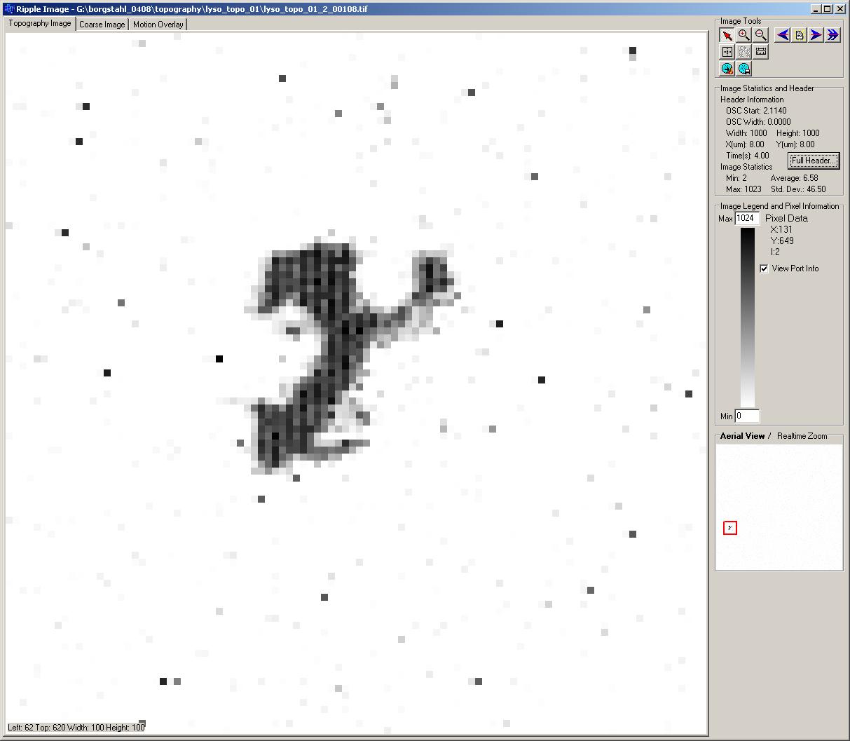
Project Settings Dialog - Topography Tab
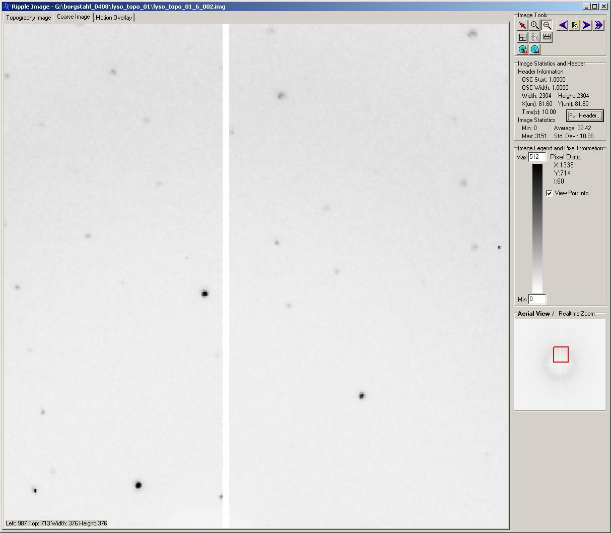
Project Settings Dialog - Coarse Tab
A project can contain any number of image windows. New image windows are created by selecting "New" from the image menu.
Image windows show frames of data for both the topography and coarse detectors. The topography camera can be positioned with respect to the coarse window when all of the experimental parameters are entered into the project settings dialog box. The image windows allow distances to be measured and intensities to evaluated. Progressing through a sequence of images allows for mosaic domain information to be estimated. There are a number of tools to aid in the analysis of the detector image.
The topography and coarse tabs contain the same information and functions. The motion control tab has one button "Beam Center" that will position the topography camera to the current beam center.
The image window contains several sections:
Image display section - Area to display detector image data.
Image statistics and header section - Area to display image information. It has a "Full Header..." button which will display the Image Header Dialog Box.
Image legend and pixel information section - Area to show the intensity legend as well as current intensity value and pixel location of the mouse when the mouse is over the display section. There is a check box to display the view port information of the image display area. This is useful if the image display area is only showing a small portion of the actual image.
Aerial View/Real Time Zoom section - Area that will show a real-time zoom of the area under the mouse when the detector is shown at full scale or an aerial view of the detector with a red box highlight the position and size of the image display area with respect to the full size detector image.
Image tools area - Collection of tools used to manipulate and view images.
Information below the tip is shown in the image and pixel information section.
Zoom in on the detector window centered at the selected location.
Zoom out from the detector window centered on the selected location.
Open the previous image in the sequence. If there are no more images then this button will be disabled.
Open a new image with a file open dialog box.
Open the next image in the sequence. If there are no more images then this button will be disabled.
Follow the images as they are collected or automatically advance to the next available image.
Select the location to use as the beam center and set the value in the project settings area.
Select the new position of for the topography detector. This option is only available in the coarse image and enabled when there is enough information in the project settings area to map locations between the coarse image and the topography detector.
Measure a linear distances on the detector surface.
Write a Matlab file to process the topography sequence.
Write the image to disk in tiff format.